|
|
1. THE SOFTWARE CRISIS |
|
The phrase software crisis alludes to a set of problems encountered in the development of computer software during the 1960s. Within this period the software industry unsuccessfully attempted to build larger and larger software systems (to match advances in hardware technology) by simply scaling up existing development techniques. As a result:
|
To address these problems the discipline of software engineering came into being. The term (coined by a NATO study group in 1967) is intended to reflect the idea that the practice of building and maintaining software systems should be as rigorous as that found in traditional engineering disciplines. |
2. SOFTWARE ENGINEERING |
|
We can define software engineering as follows: (Software engineering is) the establishment and use of sound engineering principles in order to obtain economically software that is reliable and works efficiently on real machines. This embodies a number of themes:
|
|
3. THE SOFTWARE LIFE CYCLE |
|
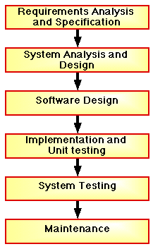
From the above one of the key themes of software engineering is that, like any other commercial product, software has a life cycle associated with it. Figure 1 shows the principal stages that comprise this life cycle. These are the standard stages that we can expect to be associated with the development of any software system (not necessarily a OO system). 
Figure 1: Processes associated with a general model of the software life cycle. Software development encompasses the middle four stages: system analysis and design, software design, implementation and unit testing, and system testing. The individual phases of the above life cycle are briefly described below. Requirements analysis and specification. Work begins by establishing and analysing the requirements of the procurer (usually the end user), i.e. determining the nature of the system to be built (in terms of hardware and software). Requirements analysis usually results in a requirements specification document or (for small software systems) a requirements specification statement. This specification then defines the "product", and thus must be accepted by both the customer and the developers. In other words it has some legal standing. Requirements analysis and specification are beyond the scope of COMP101. System Analysis and Design. The second phase is to analyse the requirements and produce a "high-level" design of the proposed system (again in terms of hardware and software). There are many approaches to system analysis and design. Software Design. The third phase is to produce a detailed design of the desired software sometimes referred to as a software specification. The idea behind a software design/specification is that it is (implementation) "language independent". You should be able to give the design to different programmers to implement in different languages and get a working result in all cases. The detailed design can be thought of as a "model" of the system that is envisaged, and its implementation its physical realisation. |
To determine whether you have produced a good design or not you should ask yourself the following, "if I gave this design to one of my colleagues would they be able to produce the software that I envisage?" If the answer to this question is "No" then you should reconsider your design. Again there are many approaches to design/ specification. We will be using diagrammatic techniques (Nassi- Shneiderman charts and control flow diagrams) supported by data tables to design our software. Unit Testing and Implementation. During implementation the design is translated into a machine-readable (and consequently executable) form. Some "unit" testing normally takes place as the implementation progresses. By unit testing we mean the testing of sub-assemblies of the program. Testing. Once the implementation has been completed it must be tested to ensure that all parts of the program behave in the manner that they are expected to behave. One straight-forward approach in which software can be tested is to identify "meaningful" test cases with which the software can be run. The results produced can then be compared with the expected results and appropriate conclusions drawn. On completion of testing the product is delivered to the customer. Maintenance As with any other commercial product, software must be maintained once it has been delivered. We can identify three categories of maintenance:
Maintenance, although perceived as being unglamorous, takes up a considerable amount of the total effort expanded throughout the software life cycle. It is difficult to quantify the amount of effort involve, but some authors claim between 50% and 70% of the total effort depending on the nature of the application. A primary aim of program development should therefore be to reduce the effort required for maintenance by designing the code with a view to "easy maintenance". Essentially the maintenance task is greatly eased by writing code that can easily be understood by persons not involved in the original production of the software. Thus anything that enhances the readability of software, and consequently its understandability is a good thing.
|
4. THE OBJECT-ORIENTATED METHODOLOGY |
|
A systematic approach to software engineering (i.e. a methodology --- a way of doing things) simplifies the process and results in software which is understandable, verifiable and reliable without stifling the creativity of the software engineer. One such methodology is the Object Oriented approach (Booch 1982), usually referred to by the acronym OOAD (Object Oriented Analysis and Design). OOAD "dove-tails" nicely with the use of object-oriented languages, such as Java, as the implementation language. Object-oriented languages encourage (enforce?) the OOAD paradigm. Thus, unlike other programming language paradigms the object-oriented paradigm is both a programming style (Object-Oriented Programming --- OOP) as well as an approach to software engineering. The principal features of the methodology are:
So what is "object orientation"? The key element of the Object Oriented methodology, as the name suggests, is the object. An object is some real world entity which a programmer wishes to "model". In Figure 2 an "object", let us call it bob (object names, by convention, commence with a lower case letter) is shown. It has many characteristics (attributes) including: 6 sides to its body, 2 arms and 2 legs. Let us also say that this particular object's function is to add up pairs of numbers. 
Figure 2: A "cube" object. In Figure 3, a similar object, let us call it mary, to that presented in Figure 2 is given (except that it has 4 legs). 
Figure 3: Another "cube" object. In OO parlance the characteristics or attributes of an object (i.e. the "number of legs" in the example given here) are referred to as its fields, and its functions (i.e. "adding up pairs of numbers" in the example given here) as methods. Collectively fields and methods are referred to as members. |
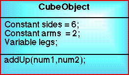
The characteristics (nature) of objects are defined by what is termed a class. In the case of Bob and Mary they might both belong to a class called CubeObject. The class CubeObject might then be described as shown in Figure 4. (Note: the form of table presented in Figure 4 is known as a class diagram and is a common diagrammatic technique used in object oriented software engineering.) 
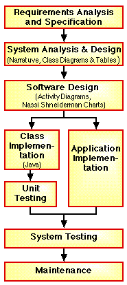
Figure 4: Class diagram for the class CubeObject. So object-orientation is a mechanism for modelling problems in terms of things known as objects which are in turn defined in terms of a class. The stages involved in the object-oriented approach can be mapped on to the stages associated with the general life cycle given in Figure 1. A suggested mapping is presented in Figure 5. Note that the diagram includes some techniques that we will be adopting (more on this later in the text). The key difference between Figure 5 and 1 is that the implementation has been divided into a class branch and an application branch. If the class part already exists (having been previously developed as part of some other application) then we can omit this branch. The class concept allows us to do this. It is this distinction between classes and applications that results in the first three of the above listed features of the methodology. Flexibility and Adaptability, and Software Reuse and Extension: Classes can be associated with many different applications (and vice-versa) and can be worked on (altered, refined or updated) in isolation. Information Hiding: A programmer working on an application need not be concerned with detail of the operation of particular classes. The fourth feature (Consistent Notation and Integration) is self-evident, unique to the OO approach and results in the fifth feature (Reliability) --- although this last is of course a claim made by all software development methodologies! 
Figure 5: Refined software engineering life cycle model for the object oriented paradigm (reference to specific tools to support the process are included in parenthesis). |
5. UNIFIED MODELLING LANGUAGE (UML) |
|
In the 1980s as increasing numbers of organisations started to convert to the OO paradigm and developed their own OOAD methodologies and procedures each using dedicated languages and notations. This proliferation of OOAD languages and notations meant that there were no standard OOAD tools available, and personnel required retraining whenever they changed organisations. By the early 1990s it was clear that a standard OOAD language and notation was needed. In 1994 the Object Management Group (OMG), a non-profit making Organisation seeking to promote the use of the OO paradigm, invited submissions for a common modelling language. A group of corporations, known as the UML partners (HP, IBM, Microsoft, Oracle, Rational Software), developed UML version 1.1 through a process of unifying a number of existing techniques, and submitted it to OMG. The submission was accepted in 1997 with OMG taken on the responsibility, as a non-profit making organisation, for its further development. Version 1.4 was released in 2001. UML does not define any particular methodology for OODA, but instead defines a set of twelve types of diagrams that can be used to support methodologies in a commonly understood manner (it is not necessary to use all 12). The available diagrams are divided into three categories: |
The lack of an accompanying UML methodology has been the cause of much academic criticism. however UML is fast becoming (summer 2002) the industry standard. It is not the intention for COMP101 students to become fully familiar with UML, this is done elsewhere, however we will be using some UML notation where appropriate. In particular we will be using Class and Activity Diagrams. |
6. THE COMP101 OBJECT ORIENTED ANALYSIS AND DESIGN (OOAD) METHODOLOGY |
7. GLOSSARY |
| Term | Definition |
|---|---|
| Object | Some real world entity which a programmer wishes to "model". |
| Class | he definition of an object, we say that an object is "an instance of a class". Alternatively we can say that an "object is a realistaion of a class". There is no limit to the number of instances of a particular class. |
| Fields | The attributes of objects belonging to a particular class (e.g. 6 sides, 2 arms and a number of legs). |
| Methods | The functions of objects belonging to a particular class (e.g. adding up pairs of numbers). |
| Members | The collective noun for the fields and methods making up a class definition |
I would like to thank: Behnoush Daneshtalab for corrections to section 6.3 supplied in November 2006.
Created and maintained by Frans Coenen. Last updated 10 February 2015